

Why this problem matters
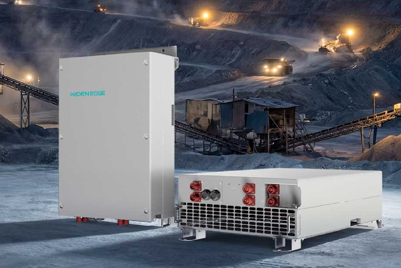
Off-grid PV systems often fail not because panels underproduce, but because the inverter and storage are mismatched to real demand. You need clear rules for matching instantaneous power, usable energy, and the conditions the system will face. That mismatch is the problem I tackle here, drawing on hands-on work with commercial sites and reference hardware like a 125kW commercial energy storage inverter to show how a reasonable design approach looks in practice.
Define the core variables — what actually governs sizing
Three independent things drive a correct inverter size: peak continuous power, required energy autonomy, and environmental/operational constraints. Call them Ppeak, Eusable, and Ops. Treat each separately, then combine.
Short checklist:
- Ppeak — highest continuous load the inverter must carry without tripping.
- Eusable — battery energy available after depth-of-discharge limits and efficiency losses.
- Ops — ambient temperature, altitude, transient loads (motors), and charging strategy.
When you read product pages, compare the spec sheet numbers to these three items. For battery-coupled systems, also check the commercial battery inverter grid/isolated modes and continuous vs. surge ratings.
Step-by-step pragmatic sizing method
Problem-driven steps that engineers actually use on site:
- Measure or estimate the peak continuous load over the critical period (Ppeak). Use the highest hour or 15-minute average, not momentary spikes.
- Decide autonomy hours (Haut). Multiply by average expected load to get Erequired = Load_avg × Haut.
- Choose battery usable capacity: Eusable = Battery_nameplate × DoD × (1 – system losses). Include charge/discharge efficiency (typical 85–95%).
- Ensure inverter continuous rating ≥ Ppeak. If motor starts or large inrushes exist, check surge capacity and use soft-start or VFDs rather than oversizing inverter by large factors.
- Verify thermal derating: if site ambient frequently exceeds 25–30 °C, derate the inverter rating per manufacturer chart.
- Calculate charge power: Solar array and charger must replenish Eusable within required window. Match PV inverter/MPPT sizing to battery charger and inverter charging limits.
Quick worked example
Goal: support a light-industrial site with 60 kW nominal load, 4 hours autonomy, and average load 40 kW during that period.
- Ppeak = 60 kW. Inverter continuous rating should be ≥ 60 kW. If 10% headroom is desired, pick 66 kW or pair parallel inverters.
- Erequired = 40 kW × 4 h = 160 kWh. Allow 10% round-trip losses → need ~178 kWh. With a battery DoD 80%, battery nameplate ≈ 223 kWh.
- If ambient temps commonly reach 40 °C, apply manufacturer derating. A nominal 60 kW inverter might be derated to 85–90% continuous; choose a model that maintains 60 kW at site conditions or add cooling.
Common mistakes that create failures
Fix these predictable errors early:
- Confusing peak demand short spikes (tens of milliseconds) with sustained peaks — use appropriate surge handling, not oversized continuous rating.
- Underestimating battery round-trip and inverter inefficiencies — always model end-to-end losses.
- Ignoring ambient derating — rooftop installations can easily add 10–20 °C above ambient air temperature.
- Mismatching charge power — PV array too small to recharge in required time, leaving the system stranded after consecutive cloudy days.
Thermal, altitude and maintenance realities
In practical deployments the environment kills more systems than design mistakes. Expect to specify: thermal derating curves, altitude corrections above 1,000–1,500 m, and a service plan for battery equalisation and firmware updates. In a commercial microgrid deployment in California, teams scheduled quarterly checks around heat seasons and still found inverter fans clogged — simple maintenance saved downtime.
Testing, commissioning and verification
Run three validation tests before signing off: continuous-load run for four hours at Ppeak, a simulated transient (motor start) test, and a recharge test that demonstrates the PV and charger return the battery to target SoC within the operational window. Record thermals, efficiency, and event logs. If anything trips, fix the weakest link: cooling, control settings, or protective thresholds.
Alternatives and when to choose them
Options exist beyond a single inverter: parallel modular inverters offer redundancy and easier service; larger central inverters can be cheaper but add single-point risk. Choose modular when uptime and phased expansion matter. Choose central when initial capital and footprint tightness dominate. Evaluate trade-offs using the three core variables: Ppeak, Eusable, and Ops.
Final synthesis
The problem-first path is straightforward: establish peak power needs, calculate usable energy with real losses and protection margins, then confirm the inverter holds that power under actual site conditions. That approach reduces surprises during commissioning and simplifies maintenance planning. For many commercial systems, matching sizing work to proven hardware and service capability is what keeps systems running — which is the practical value delivered by WidenEdge.