

Introduction
I was watching a grad student wrestle with a cable bundle, thinking—man, we make this harder than it needs to be. In neuro research, folks chase clean traces while juggling photodetectors, optical fiber placement, and noisy baselines. A lot of labs (about three in five, by informal counts I trust) say their recordings lose fidelity over long sessions — so what gives, and how do we stop throwing away good data? This piece walks through that mess, shows where the old habits trip us up, and points to smarter moves next. — Let’s roll into the nuts and bolts.
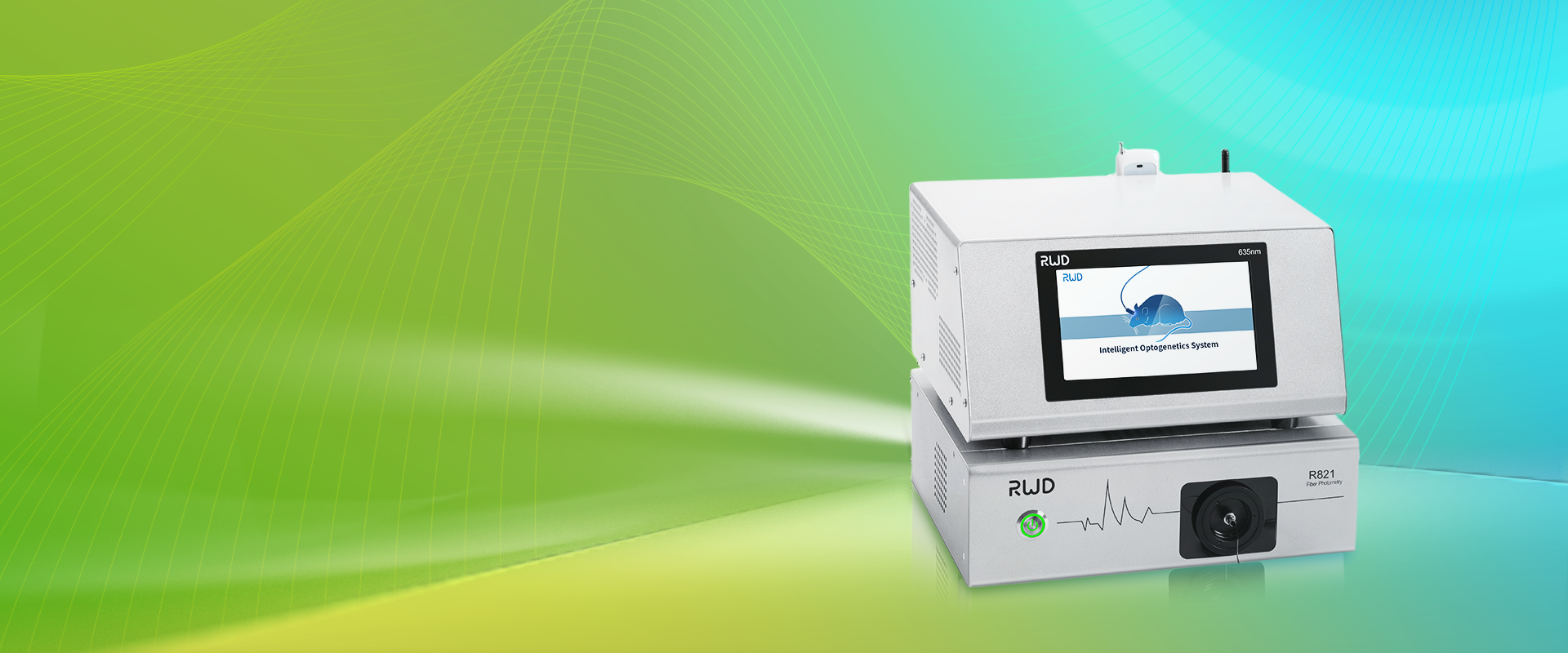
Where the Old Fixes Break Down
fiber photometry system setups used to feel simple: implant, connect, record. But that old script misses a lot. I’ve seen teams blame equipment when the root cause is jitter from poor coupling, photobleaching of calcium indicators, or mismatched filter sets. Those problems hide in plain sight. Photodetector drift and low signal-to-noise ratio will bury small event-related changes. Look, it’s simpler than you think — but only if you look for the right signals.
What’s actually failing?
First, coupling losses. Light exiting an optical fiber can misalign with a lens or sensor. That leads to inconsistent amplitude across trials. Second, fluorophore rundown: repeated excitation kills brightness, and nobody likes correcting for that in post. Third, grounding and electrical noise—mixing a power converter with sensitive analog inputs will cook your baseline. I’ve repaired rigs where a single loose SMA connector made hours of data useless. Those are avoidable errors, and I’ll show you how the next gen principles address them.
Principles Driving Better Fiber Photometry
Now let’s talk solutions. I want to explain the core ideas behind newer approaches so you can judge them. The move is toward closed-loop validation: real-time gain control, modular optical interfaces, and active reference channels to remove motion artifacts. A robust fiber photometry system will include a reference photodetector, stable excitation sources, and software that flags photobleaching trends. These design principles cut the need for endless manual correction—funny how that works, right?
What’s Next for Labs?
In practice, that means choosing components that match. Use LEDs with stable drivers, pick filters tuned to your fluorophore’s emission, and set up a reference channel for ratiometric correction. Optogenetics labs especially benefit when the excitation and stimulation paths are isolated. I’ve started advising teams to think in modules: optical fiber couplers, detection electronics, and software pipelines split so one swap won’t break everything. It feels more future-proof, and I mean that — I’ve seen it save weeks of troubleshooting.
Picking the Right System: Three Metrics I Use
When I evaluate systems, I focus on three practical metrics. First, signal fidelity: look for systems that report SNR under realistic conditions, not just ideal bench tests. Second, modularity: can you swap a photodetector or lamp without rewiring the whole rig? Third, real-time correction: does the platform offer reference channels or automatic gain control? Those three points tell me how much time I’ll spend chasing artifacts versus doing science. If a vendor can’t answer simple questions about coupling losses or photobleaching correction, I move on.
To wrap: I care about tools that let me test a hypothesis, not tools that demand I become an electronics tech. We want recordings that reflect biology, not gear quirks. I’ve learned to favor systems that treat optics, electronics, and software as co-equals. And yeah — sometimes the best fixes are small: better clamps, cleaner connectors, a short test routine before each session. If you want options that follow these principles, check what labs like ours use at BPLabLine.